LV ABC (Self Supporting & Supporting Core)
Application
Aerial Bundle Cable (ABC cable) is a very innovative concept for overhead power distribution as compared to the conventional bare conductor overhead distribution system.
It provides higher level of safety and reliability, lower power losses and ultimate system economy by reducing installation, maintenance and operative cost.
LV Aerial Bundle Cables are designed to supply 600/1000 volt aerial service for temporary service at construction sites, as a service drop (power pole to service entrance), as a secondary cable (pole to pole) or street lighting.
This over-head cable provides reinforced insulation acc. IEC 61140 and fulfill therefore Class II acc. IEC 61140. It is not flame retardant. But this could be if requested change to a flame retardant cable.
Standard
International Electrotechnical Commission International Standards- TNB Specification(IEC 60502)
Australia New Zealand Standard-AS/NZS 3560-1 standards
French Standard-NFC 33-209
HD 626 S1
British Standard-BS 7870
MV ABC (3.8/6.6kV-19/33kV)LV & MV Aerial Bundle Cable (ABC) Overhead Distribution Lines
Application
Aerial bundled cables are mainly used for secondary overhead lines on poles or as feeders to residential premises.
Standard
International Electrotechnical Commission International Standards-IEC 60502
Australia New Zealand Standard-AS/NZS 3599-1 standards
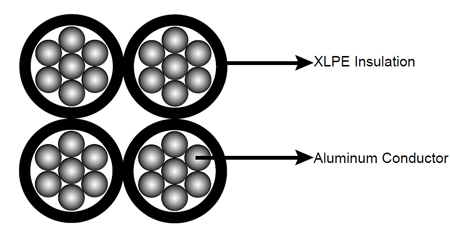
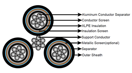
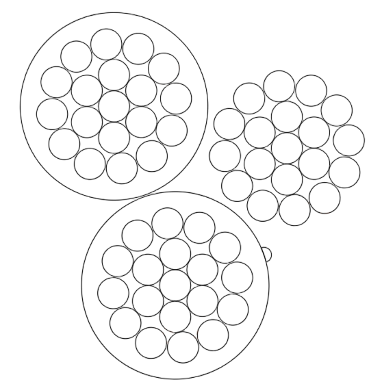
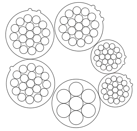
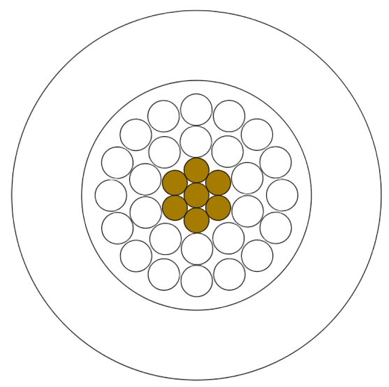
Construction of Aerial Bundle Cable (ABC Cable)
| Item | Core | Drawing | Component Description |
|
Low Voltage Aerial Bundle Cable |
1 Core |
|
– Conductor: Aluminium or Aluminium Alloy |
|
2 Core |
|
– Conductor: Aluminium or Aluminium Alloy |
|
|
3 Core |
 |
– Conductor: Aluminium or Aluminium Alloy |
|
|
4 Core |
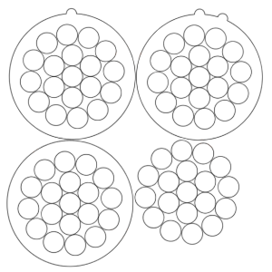 |
– Conductor: Aluminium or Aluminium Alloy |
|
|
5 Core |

|
– Conductor: Aluminium or Aluminium Alloy |
|
|
6 Core |
|
More cores are all Avilable, Please feel free to contact Xinfeng Cable. |
|
|
Medium Voltage Aerial Bundle Cable |
1 Core |
|
– Conductor: Aluminium or Aluminium Alloy |
|
3 Core + Messenger Wire |

|
– Conductor: Aluminium or Aluminium Alloy |
Parameter
0.6/1kv IEC 60502&TNB
| Number of cores x nominal cross section | min. breaking load of conductor strand | Current rating in the air | Outer diameter | Total weight |
| mm^2 | kN | A | mm | kg/km |
| 1×16+1x 25 RM | 6.4 | 61 | 15.3 | 160 |
| 3×16+1x 25 RM | 6.4 | 61 | 19.0 | 290 |
| 3×25+1x 25 RM | 6.4 | 84 | 23.2 | 400 |
| 3×35+1x 25 RM | 6.4 | 104 | 25.6 | 500 |
| 3×50+1x 35 RM | 8.9 | 129 | 30.0 | 680 |
| 3×70+1x 50 RM | 12.1 | 167 | 34.9 | 920 |
| 3×95+1x 70 RM | 18.0 | 209 | 40.6 | 1270 |
| 3×120+1x 70 RM | 18.0 | 246 | 44.1 | 1510 |
| 3×150+1x 95 RM | 24.2 | 283 | 49.2 | 1870 |
| 3×185+1×120 RM | 30.8 | 332 | 54.9 | 2340 |
| 3×25+1×25+1×16 RM | 6.4 | 84 | 23.2 | 470 |
| 3×35+1×25+1×16 RM | 6.4 | 104 | 25.6 | 560 |
| 3×50+1×35+1×16 RM | 8.9 | 129 | 30.0 | 740 |
| 3×70+1×50+1×16 RM | 12.1 | 167 | 34.9 | 980 |
| 3×95+1×70+1×16 RM | 18.0 | 209 | 40.6 | 1330 |
| 3×120+1×70+1×16 RM | 18.0 | 246 | 44.1 | 1580 |
| 3×150+1×95+1×16 RM | 24.2 | 283 | 49.2 | 1940 |
| 3×185+1×120+1×16 RM | 30.8 | 332 | 54.9 | 2410 |
0.6/1kv AS/NZS 3560.1
| Number of cores x nominal cross section | min. breaking load of conductor strand | Current rating in the air | Outer diameter | Total weight |
| mm^2 | kN | A | mm | kg/km |
| 2×16 RM | 4.4 | 78 | 15.0 | 140 |
| 2×25 RM | 7.0 | 105 | 17.6 | 210 |
| 2×35 RM | 9.8 | 125 | 19.6 | 270 |
| 2×50 RM | 11.4 | 150 | 22.8 | 370 |
| 2×95 RM | 15.3 | 230 | 30.6 | 680 |
| 3×25 RM | 8.8 | 97 | 19.0 | 310 |
| 3×35 RM | 9.8 | 120 | 21.1 | 410 |
| 3×50 RM | 11.4 | 140 | 24.6 | 550 |
| 4×16 RM | 8.8 | 74 | 18.1 | 290 |
| 4×25 RM | 14.0 | 97 | 21.2 | 410 |
| 4×35 RM | 19.6 | 120 | 23.7 | 550 |
| 4×50 RM | 28.0 | 140 | 27.5 | 740 |
| 4×70 RM | 39.2 | 175 | 31.9 | 1000 |
| 4×95 RM | 53.2 | 215 | 36.9 | 1370 |
| 4×120 RM | 67.2 | 250 | 40.6 | 1690 |
| 4×150 RM | 84.0 | 280 | 43.9 | 2020 |
0.6/1kv DES/LVC/ABC&IEC 60502
| Number of cores x nominal cross section | min. breaking load of conductor strand | Current rating in the air | Outer diameter | Total weight |
| mm^2 | kN | A | mm | kg/km |
| 4×25 RM | 3.5 | 84 | 21.5 | 420 |
| 4×35 RM | 4.9 | 104 | 23.9 | 550 |
| 4×120+1×25 RM | 16.8 | 246 | 43.8 | 1800 |
| 4×185+1×25 RM | 25.9 | 332 | 50.7 | 2700 |
0.6/1kv NFC 33-209
| No. of Conductor and Cross Section Area |
Phase Core | Neutral Core | Street Lighting Core | Complete Cable | ||||||||||
| No. and Section Area |
No. of Wire | Dia. of Conductor (Approx.) |
Insulation Thickness |
No. and Section Area |
No. of Wire | Dia. of Conductor (Approx.) |
Insulation Thickness |
No. and Section area |
No. of Wires | Diameter of conductor |
Insulation Thickness |
Overall Diameter (Approx.) |
Weight (Approx.) |
|
| mm2 | mm2 | No. | mm | mm | mm2 | No. | mm | mm | mm2 | No. | mm | mm | mm | kg/km |
| 2X10 | 2X10 | 7 | 1.0 | |||||||||||
| 2x16 | 2x16 | 7 | 4.8 | 1.2 | - | - | - | - | - | - | - | - | 14.2 | 126 |
| 2x25 | 2x25 | 7 | 6.0 | 1.4 | - | - | - | - | - | - | - | - | 17.6 | 194 |
| 2x35 | 2x35 | 7 | 7.0 | 1.6 | - | - | - | - | - | - | - | - | 20.4 | 266 |
| 2x50 | 2x50 | 7 | 8.1 | 1.6 | - | - | - | - | - | - | - | - | 22.6 | 341 |
| 4x16 | 4x16 | 7 | 4.8 | 1.2 | - | - | - | - | - | - | - | - | 17.2 | 252 |
| 4x25 | 4x25 | 7 | 6.0 | 1.4 | - | - | - | - | - | - | - | - | 21.2 | 388 |
| 4x35 | 4x35 | 7 | 7.0 | 1.6 | - | - | - | - | - | - | - | - | 24.6 | 533 |
| 3x25+54.6 | 3x25 | 7 | 6.0 | 1.4 | 1x54.6 | 7 | 9.45 | 1.6 | - | - | - | - | 23.6 | 496 |
| 3x25+54.6+1x16 | 3x25 | 7 | 6.0 | 1.4 | 1x54.6 | 7 | 9.45 | 1.6 | 1x16 | 7 | 4.8 | 1.2 | 24.9 | 560 |
| 3x25+54.6+2x16 | 3x25 | 7 | 6.0 | 1.4 | 1x54.6 | 7 | 9.45 | 1.6 | 2x16 | 7 | 4.8 | 1.2 | 26.6 | 624 |
| 3x35+54.6 | 3x35 | 7 | 7.0 | 1.6 | 1x54.6 | 7 | 9.45 | 1.6 | - | - | - | - | 26.1 | 604 |
| 3x35+54.6+1x16 | 3x35 | 7 | 7.0 | 1.6 | 1x54.6 | 7 | 9.45 | 1.6 | 1x16 | 7 | 4.8 | 1.2 | 27.2 | 668 |
| 3x35+54.6+2x16 | 3x35 | 7 | 7.0 | 1.6 | 1x54.6 | 7 | 9.45 | 1.6 | 2x16 | 7 | 4.8 | 1.2 | 28.7 | 732 |
| 3x50+54.6 | 3x50 | 7 | 8.1 | 1.6 | 1x54.6 | 7 | 9.45 | 1.6 | - | - | - | - | 28.1 | 716 |
| 3x50+54.6+1x16 | 3x50 | 7 | 8.1 | 1.6 | 1x54.6 | 7 | 9.45 | 1.6 | 1x16 | 7 | 4.8 | 1.2 | 28.9 | 780 |
| 3x50+54.6+2x16 | 3x50 | 7 | 8.1 | 1.6 | 1x54.6 | 7 | 9.45 | 1.6 | 2x16 | 7 | 4.8 | 1.2 | 30.3 | 844 |
| 3x70+54.6 | 3x70 | 12 | 10.0 | 1.8 | 1x54.6 | 7 | 9.45 | 1.6 | - | - | - | - | 32.2 | 940 |
| 3x70+54.6+1x16 | 3x70 | 12 | 10.0 | 1.8 | 1x54.6 | 7 | 9.45 | 1.6 | 1x16 | 7 | 4.8 | 1.2 | 32.7 | 1004 |
| 3x70+54.6+2x16 | 3x70 | 12 | 10.0 | 1.8 | 1x54.6 | 7 | 9.45 | 1.6 | 2x16 | 7 | 4.8 | 1.2 | 33.8 | 1068 |
| 3x70+54.6+1x25 | 3x70 | 12 | 10.0 | 1.8 | 1x54.6 | 7 | 9.45 | 1.6 | 1x25 | 7 | 6.0 | 1.4 | 33.6 | 1038 |
| 3x70+54.6+2x25 | 3x70 | 12 | 10.0 | 1.8 | 1x54.6 | 7 | 9.45 | 1.6 | 2x25 | 7 | 6.0 | 1.4 | 35.5 | 1137 |
| 3x70+70 | 3x70 | 12 | 10.0 | 1.8 | 1x70 | 7 | 10.20 | 1.5 | - | - | - | - | 32.1 | 970 |
| 3x70+70+1x16 | 3x70 | 12 | 10.0 | 1.8 | 1x70 | 7 | 10.20 | 1.5 | 1x16 | 7 | 4.8 | 1.2 | 32.5 | 1035 |
| 3x70+70+2x16 | 3x70 | 12 | 10.0 | 1.8 | 1x70 | 7 | 10.20 | 1.5 | 2x16 | 7 | 4.8 | 1.2 | 33.6 | 1099 |
| 3x95+70 | 3x95 | 19 | 11.7 | 1.8 | 1x70 | 7 | 10.20 | 1.5 | - | - | - | - | 35.6 | 1212 |
| 3x95+70+1x16 | 3x95 | 19 | 11.7 | 1.8 | 1x70 | 7 | 10.20 | 1.5 | 1x16 | 7 | 4.8 | 1.2 | 35.7 | 1276 |
| 3x95+70+2x16 | 3x95 | 19 | 11.7 | 1.8 | 1x70 | 7 | 10.20 | 1.5 | 2x16 | 7 | 4.8 | 1.2 | 36.6 | 1340 |
| 3x120+70 | 3x120 | 19 | 13.0 | 1.8 | 1x70 | 7 | 10.20 | 1.5 | - | - | - | - | 38.0 | 1439 |
| 3x120+70+1x16 | 3x120 | 19 | 13.0 | 1.8 | 1x70 | 7 | 10.20 | 1.5 | 1x16 | 7 | 4.8 | 1.2 | 37.8 | 1503 |
| 3x120+70+2x16 | 3x120 | 19 | 13.0 | 1.8 | 1x70 | 7 | 10.20 | 1.5 | 2x16 | 7 | 4.8 | 1.2 | 38.6 | 1567 |
| 3x150+70 | 3x150 | 19 | 14.4 | 1.7 | 1x70 | 7 | 10.20 | 1.5 | - | - | - | - | 40.2 | 1650 |
| 3x150+70+1x16 | 3x150 | 19 | 14.4 | 1.7 | 1x70 | 7 | 10.20 | 1.5 | 1x16 | 7 | 4.8 | 1.2 | 39.8 | 1714 |
| 3x150+70+2x16 | 3x150 | 19 | 14.4 | 1.7 | 1x70 | 7 | 10.20 | 1.5 | 2x16 | 7 | 4.8 | 1.2 | 40.4 | 1778 |
| 3x120+95 | 3x120 | 19 | 13.0 | 1.8 | 1x95 | 19 | 12.50 | 1.6 | - | - | - | - | 39.5 | 1526 |
| 3x120+95+1x16 | 3x120 | 19 | 13.0 | 1.8 | 1x95 | 19 | 12.50 | 1.6 | 1x16 | 7 | 4.8 | 1.2 | 39.5 | 1590 |
| 3x120+95+2x16 | 3x120 | 19 | 13.0 | 1.8 | 1x95 | 19 | 12.50 | 1.6 | 2x16 | 7 | 4.8 | 1.2 | 39.8 | 1654 |
| 3x150+95 | 3x150 | 19 | 14.4 | 1.7 | 1x95 | 19 | 12.50 | 1.6 | - | - | - | - | 41.7 | 1736 |
| 3x150+95+1x16 | 3x150 | 19 | 14.4 | 1.7 | 1x95 | 19 | 12.50 | 1.6 | 1x16 | 7 | 4.8 | 1.2 | 41.7 | 1800 |
| 3x150+95+2x16 | 3x150 | 19 | 14.4 | 1.7 | 1x95 | 19 | 12.50 | 1.6 | 2x16 | 7 | 4.8 | 1.2 | 41.6 | 1865 |
0.6/1kv HD 626 S1
| Number of cores x nominal cross section | min. breaking load of conductor strand | Current rating in the air | Outer diameter | Total weight |
| mm^2 | kN | A | mm | kg/km |
| 2x 16 RM | 1,910 | 2,5 | 72 | 147 |
| 2x 25 RM | 1,200 | 4,0 | 107 | 208 |
| 2x 35 RM | 0,868 | 5,5 | 132 | 277 |
| 2x 50 RM | 0,641 | 8,0 | 165 | 361 |
| 4x 16 RM | 1,910 | 2,5 | 72 | 286 |
| 4x 25 RM | 1,200 | 4,0 | 107 | 430 |
| 4x 35 RM | 0,868 | 5,5 | 132 | 553 |
| 4x 50 RM | 0,641 | 8,0 | 165 | 746 |
| 4x 70 RM | 0,443 | 10,7 | 205 | 1009 |
| 4x 95 RM | 0,320 | 13,7 | 240 | 1332 |
| 4x 120 RM | 0,253 | 18,6 | 290 | 1632 |
| 4x 35 + 1x 35 RM | 0,868/0,868 | 5,5/5,5 | 132/132 | 694 |
| 4x 50 + 1x 25 RM | 0,641/1,200 | 8,0/4,0 | 165/107 | 814 |
| 4x 50 + 1x 35 RM | 0,641/0,868 | 8,5/5,5 | 165/132 | 845 |
| 4x 70 + 1x 25 RM | 0,443/1,200 | 10,7/4,0 | 205/107 | 1105 |
| 4x 70 + 2x 25 RM | 0,443/1,200 | 10,7/4,0 | 205/107 | 1217 |
| 4x 70 + 1x 35 RM | 0,443/0,868 | 10,7/5,5 | 205/132 | 1150 |
| 4x 70 + 2x 35 RM | 0,443/0,868 | 10,7/5,5 | 205/132 | 1289 |
| 4x 95 + 1x 25 RM | 0,320/1,200 | 13,7/4,0 | 240/107 | 1438 |
| 4x 95 + 1x 35 RM | 0,320/0,868 | 13,7/5,5 | 240/132 | 1467 |
| 4x 95 + 2x 25 RM | 0,320/1,200 | 13,7/4,0 | 240/107 | 1544 |
0.6/1kv BS 7870-5
| Number of cores x nominal cross section | max. conductor- resistance | min. breaking load of conductor strand | Current rating in the air | Outer diameter | Total weight |
| mm^2 | Ohm/km | kN | A | mm | kg/km |
| 1x 16 RM | 1,910 | 2,5 | 72 | 80 | 74 |
| 1x 25 RM | 1,200 | 4,0 | 107 | 90 | 106 |
| 1x 35 RM | 0,868 | 5,5 | 132 | 105 | 138 |
| 1x 50 RM | 0,641 | 8,0 | 165 | 118 | 182 |
| 1x 70 RM | 0,443 | 10,7 | 205 | 130 | 252 |
| 1x 95 RM | 0,320 | 13,7 | 240 | 154 | 333 |
| 1x 120 RM | 0,253 | 18,6 | 290 | 170 | 408 |
| 1x 150 RM | 0,206 | 23,2 | 334 | 190 | 502 |
| 1x 185 RM | 0,164 | 28,7 | 389 | 210 | 611 |
| 1x 240 RM | 0,125 | 37,2 | 467 | 240 | 801 |
| 2x 16 RM | 1,910 | 2,5 | 72 | 156 | 147 |
| 2x 25 RM | 1,200 | 4,0 | 107 | 180 | 208 |
| 2x 35 RM | 0,868 | 5,5 | 132 | 200 | 277 |
| 2x 50 RM | 0,641 | 8,0 | 165 | 235 | 361 |
| 2x 70 RM | 0,443 | 10,7 | 205 | 254 | 505 |
| 2x 95 RM | 0,320 | 13,7 | 240 | 303 | 666 |
| 2x 150 RM | 0,206 | 23,2 | 334 | 380 | 1004 |
| 4x 16 RM | 1,910 | 2,5 | 72 | 188 | 286 |
| 4x 25 RM | 1,200 | 4,0 | 107 | 212 | 430 |
| 4x 35 RM | 0,868 | 5,5 | 132 | 241 | 553 |
| 4x 50 RM | 0,641 | 8,0 | 165 | 278 | 746 |
| 4x 70 RM | 0,443 | 10,7 | 205 | 318 | 1009 |
| 4x 95 RM | 0,320 | 13,7 | 240 | 378 | 1332 |
| 4x 120 RM | 0,253 | 18,6 | 290 | 544 | 1632 |
| 4x 50 + 1x 25 RM | 0,641/1,200 | 8,0/4,0 | 165/107 | 319 | 814 |
| 4x 50 + 1x 35 RM | 0,641/0,868 | 8,5/5,5 | 165/132 | 319 | 845 |
| 4x 70 + 1x 25 RM | 0,443/1,200 | 10,7/4,0 | 205/107 | 360 | 1105 |
| 4x 70 + 2x 25 RM | 0,443/1,200 | 10,7/4,0 | 205/107 | 400 | 1217 |
| 4x 95 + 1x 25 RM | 0,320/1,200 | 13,7/4,0 | 240/107 | 418 | 1438 |
| 4x 95 + 2x 25 RM | 0,320/1,200 | 13,7/4,0 | 240/107 | 420 | 1544 |
| 4×120 + 1x 25 RM | 0,253/1,200 | 18,6/4,0 | 290/107 | 590 | 2050 |
IEC 60502 6.35/11 kV
| Number of Cores x Nominal Cross Section | Phase Conductor | Messenger Suspension Unit | Continuous current rating at 300C ambient temp | ||||
| Stranding | Nominal Sectional Area | Maximum Conductor Resistance | Stranding | Nominal Sectional Area | Breaking Load | ||
| No.×mm^2 | No.×mm | mm^2 | Ω/Km | No.×mm | mm^2 | KN | A |
| 3X50 + 1X25 | 19/1.78 | 50 | 0.641 | 7/3.0 | 50 | 60 | 116 |
| 3X70 + 1X50 | 19/.14 | 70 | 0.443 | 7/3.15 | 50 | 62 | 210 |
| 3X95+ 1X50 | 19/2.52 | 95 | 0.32 | 7/3.0 | 50 | 60 | 173 |
| 3X185+1X120 | 37/2.52 | 185 | 0.164 | 7/4.67 | 120 | 150 | 259 |
| 3X150 +1X50 | 37/2.25 | 150 | 0.206 | 7/3.15 | 50 | 62 | 365 |
| 3X240 +1X50 | 61/2.25 | 240 | 0.125 | 7/3.15 | 50 | 62 | 500 |
IEC 60502 19/33 kV
| Number of Cores x Nominal Cross Section | Phase Conductor | Messenger Suspension Unit | Continuous current rating at 300C ambient temp | ||||
| Stranding | Nominal Sectional Area | Maximum Conductor Resistance | Stranding | Nominal Sectional Area | Breaking Load | ||
| No.×mm^2 | No.×mm | mm^2 | Ω/Km | No.×mm | mm^2 | KN | A |
| 3X50 + 1X50 | 19/1.78 | 50 | 0.641 | 7/3.0 | 50 | 60 | 165 |
| 3X150+ 1X50 | 37/2.25 | 150 | 0.206 | 7/3.0 | 50 | 60 | 315 |
| 3X185+1X70 | 37/2.52 | 185 | 0.164 | 7/3.57 | 70 | 91 | 355 |
| 3X70 +1X50 | 19/2.14 | 7 | 0.443 | 7/3.15 | 50 | 62 | 250 |
| 3X150 +1X50 | 37/2.25 | 150 | 0.206 | 7/3.15 | 50 | 62 | 370 |
AS/NZS 3599 Part 1 6.35/11 KV Al/XLPE /HDPE Non-Screened
| Number of Cores x Nominal Cross Section | Phase Conductor | Messenger Suspension Unit | Nominal Sectional Area | Breaking Load | |||
| Diameter of Conductor | Thickness of Insulation | Thickness of Insulation Screen | Thickness of Sheath | Stranding | |||
| No.×mm^2 | mm | mm | mm | mm | No.×mm | mm^2 | KN |
| 3×35 | 6.9 | 3.4 | 0.8 | 1.2 | 7/4.75 | 52.4 | 1370 |
| 3×50 | 8.1 | 3.4 | 0.8 | 1.2 | 7/4.75 | 54.6 | 1530 |
| 3×70 | 9.7 | 3.4 | 0.8 | 1.2 | 7/4.75 | 57.8 | 1790 |
| 3×95 | 11.4 | 3.4 | 0.8 | 1.2 | 7/4.75 | 61.3 | 2100 |
| 3×120 | 12.8 | 3.4 | 0.8 | 1.2 | 19/3.50 | 67.3 | 2540 |
| 3×150 | 14.2 | 3.4 | 0.8 | 1.2 | 19/3.50 | 70.1 | 2840 |
| 3×185 | 15.7 | 3.4 | 0.8 | 1.2 | 19/3.50 | 73.1 | 3190 |
AS/NZS 3599 Part 1 6.35/11 kV AL/XLPE /CWS/HDPE Screened
| Number of Cores x Nominal Cross Section | Diameter of Conductor | Thickness of Insulation | Thickness of Insulation Screen | Copper Wire Screen Stranding | Thickness of Sheath | Galvanized Steel Wire Stranding | Nominal Sectional Area | Breaking Load |
| No.×mm^2 | mm | mm | mm | No.×mm | mm | No.×mm | mm^2 | KN |
| Light Duty Screen | ||||||||
| 3×35 | 6.9 | 3.4 | 0.8 | 25/0.85 | 1.8 | 7/2.00 | 54.1 | 1820 |
| 3×35 | 6.9 | 3.4 | 0.8 | 25/0.85 | 1.8 | 19/2.00 | 58.1 | 2130 |
| 3×50 | 8.1 | 3.4 | 0.8 | 25/0.85 | 1.8 | 19/2.00 | 60.4 | 2300 |
| 3×70 | 9.7 | 3.4 | 0.8 | 25/0.85 | 1.8 | 19/2.00 | 63.6 | 2570 |
| 3×95 | 11.4 | 3.4 | 0.8 | 25/0.85 | 1.8 | 19/2.00 | 67.0 | 2900 |
| 3×120 | 12.8 | 3.4 | 0.8 | 25/0.85 | 1.8 | 19/2.00 | 69.8 | 3190 |
| 3×150 | 14.2 | 3.4 | 0.8 | 25/0.85 | 1.9 | 19/2.00 | 73.0 | 3530 |
| 3×185 | 15.7 | 3.4 | 0.8 | 25/0.85 | 1.9 | 19/2.00 | 76.0 | 3890 |
| Heavy Duty Screen | ||||||||
| 3×35 | 6.9 | 3.4 | 0.8 | 40/0.85 | 1.8 | 7/2.00 | 54.1 | 2050 |
| 3×35 | 6.9 | 3.4 | 0.8 | 40/0.85 | 1.8 | 19/2.00 | 58.1 | 2360 |
| 3×50 | 8.1 | 3.4 | 0.8 | 23/1.35 | 1.8 | 19/2.00 | 62.4 | 2820 |
| 3×70 | 9.7 | 3.4 | 0.8 | 32/1.35 | 1.8 | 19/2.00 | 65.6 | 3440 |
| 3×95 | 11.4 | 3.4 | 0.8 | 39/1.35 | 1.8 | 19/2.00 | 69.0 | 4030 |
| 3×120 | 12.8 | 3.4 | 0.8 | 39/1.35 | 1.8 | 19/2.00 | 71.8 | 4320 |
| 3×150 | 14.2 | 3.4 | 0.8 | 39/1.35 | 1.9 | 19/2.00 | 75.0 | 4670 |
| 3×185 | 15.7 | 3.4 | 0.8 | 39/1.35 | 1.9 | 19/2.00 | 78.0 | 5020 |
AS/NZS 3599 Part 1 12.7/22 kV AL/XLPE /HDPE Non-Screened
| Number of Cores x Nominal Cross Section | Phase Conductor | Messenger Suspension Unit | Nominal Sectional Area | Breaking Load | |||
| Diameter of Conductor | Thickness of Insulation | Thickness of Insulation Screen | Thickness of Sheath | Stranding | |||
| No.×mm^2 | mm | mm | mm | mm | No.×mm | mm^2 | KN |
| 3×35 | 6.9 | 5.5 | 0.8 | 1.2 | 7/4.75 | 61.0 | 1780 |
| 3×50 | 8.1 | 5.5 | 0.8 | 1.2 | 7/4.75 | 63.3 | 1970 |
| 3×70 | 9.7 | 5.5 | 0.8 | 1.2 | 7/4.75 | 66.5 | 2260 |
| 3×95 | 11.4 | 5.5 | 0.8 | 1.2 | 7/4.75 | 69.9 | 2600 |
| 3×120 | 12.8 | 5.5 | 0.8 | 1.2 | 19/3.50 | 75.9 | 3070 |
| 3×150 | 14.2 | 5.5 | 0.8 | 1.2 | 19/3.50 | 78.7 | 3390 |
| 3×185 | 15.7 | 5.5 | 0.8 | 1.2 | 19/3.50 | 81.7 | 3760 |
AS/NZS 3599 Part 1 12.7/22 kV AL/XLPE /CWS/HDPE Screened
| Number of Cores x Nominal Cross Section | Diameter of Conductor | Thickness of Insulation | Thickness of Insulation Screen | Copper Wire Screen Stranding | Thickness of Sheath | Galvanized Steel Wire Stranding | Nominal Sectional Area | Breaking Load |
| No.×mm^2 | mm | mm | mm | No.×mm | mm | No.×mm | mm^2 | KN |
| Light Duty Screen | ||||||||
| 3×35 | 6.9 | 5.5 | 0.8 | 25/0.85 | 1.8 | 7/2.00 | 62.7 | 2280 |
| 3×35 | 6.9 | 5.5 | 0.8 | 25/0.85 | 1.8 | 19/2.00 | 66.7 | 2580 |
| 3×50 | 8.1 | 5.5 | 0.8 | 25/0.85 | 1.8 | 19/2.00 | 69.0 | 2780 |
| 3×70 | 9.7 | 5.5 | 0.8 | 25/0.85 | 1.9 | 19/2.00 | 72.6 | 3110 |
| 3×95 | 11.4 | 5.5 | 0.8 | 25/0.85 | 1.9 | 19/2.00 | 76.0 | 3460 |
| 3×120 | 12.8 | 5.5 | 0.8 | 25/0.85 | 2.0 | 19/2.00 | 79.2 | 3810 |
| 3×150 | 14.2 | 5.5 | 1.0 | 25/0.85 | 2.0 | 19/2.00 | 82.8 | 4230 |
| 3×185 | 15.7 | 5.5 | 1.0 | 25/0.85 | 2.1 | 19/2.00 | 86.2 | 4650 |
| Heavy Duty Screen | ||||||||
| 3×35 | 6.9 | 5.5 | 0.8 | 40/0.85 | 1.8 | 7/2.00 | 62.7 | 2510 |
| 3×35 | 6.9 | 5.5 | 0.8 | 40/0.85 | 1.8 | 19/2.00 | 66.7 | 2810 |
| 3×50 | 8.1 | 5.5 | 0.8 | 23/1.35 | 1.8 | 19/2.00 | 71.0 | 3300 |
| 3×70 | 9.7 | 5.5 | 0.8 | 32/1.35 | 1.9 | 19/2.00 | 74.6 | 3970 |
| 3×95 | 11.4 | 5.5 | 0.8 | 39/1.35 | 1.9 | 19/2.00 | 78.0 | 4600 |
| 3×120 | 12.8 | 5.5 | 0.8 | 39/1.35 | 2.0 | 19/2.00 | 81.2 | 4950 |
| 3×150 | 14.2 | 5.5 | 1.0 | 39/1.35 | 2.0 | 19/2.00 | 84.8 | 5360 |
| 3×185 | 15.7 | 5.5 | 1.0 | 39/1.35 | 2.1 | 19/2.00 | 88.2 | 5790 |