Application
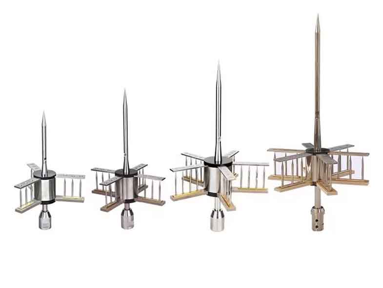
The specific function of PDC lightning rod is producing an upward stream of ionized particles that will channel the
eventual electrical discharge from its origin.
There is a difference in the electrical potential between the discharger (that has the same potential than the air around it) and
both the air terminal tip and the deflection ensemble (they have the same potential than earth). This difference increases as
atmospheric potential becomes higher because of the imminent lightning strike.
Knowing the value of this difference Δt allows us to make a relation between time and propagation speed of the electrical
discharge, and, consequently, to calculate the lightning impact distance and the protection radium that offers each lightning rod
model (see table below).
Knowing this value allows for the selection of the most appropriate lightning rod model taking into account the characteristics of
the structure we want to protect and the level of protection needed according the norms UNE 21.186:2011, NFC 17.102:2011
and NP4426:2013.
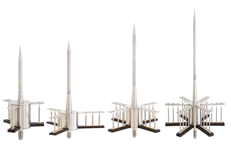
Product Structure
1. Central collecting rod;
2. Reflector;
3. Trigger device;
4. Exciter;
5. Exciter fixing plate;
6. Exciter is insulated from reflector and central collecting rod;
7. Reflector and central collecting rod have good electrical connection with the ground;
8. Exciter base is made of synthetic resin, suitable for any corrosive environment
protection levels
technical features
characteristics & benefits
· 100% of efficacy in discharge capture.
· High level of protection.
· Electrical continuity guaranteed. The device doesn't offer any
resistance to discharge conduction.
· Lightning rod without electrical components. Maximum
durability guaranteed.
· Maximum accepted current 200kA (10/350).
· PDC preserves its initial properties after each
discharge.
· As it's built only with non electronic elements, it doesn't have
replaceable parts
· It doesn't require external power supply.
· Operation guaranteed in any atmospheric condition.
· High resistance to temperature. Maximum temperature: 125ºC.
· High resistance to wheather conditions and corrosive
atmospheres.
· Maintenance free
technical specifications:
· It has a double ESE (Early Streamer Emission) system:
· An early streamer device that produces the upward
emission.
· An electro atmospheric condenser.
· An atmospheric accelerator.
· An external structure made from stainless steel AISI 316L.
· Early Streamer Emission system made from stainless steel
AISI 316L and polyamide PA66.
Its effective operation in any atmospheric condition and
environment is thus guaranteed.
Installation
· The tip of the lightning rod should be located, at least two meters above the highest building to be protected.
· A head-mast adapter piece is required in order to attach the lightning rod to the mast selected for its installation.
· Wiring on the roofs should be protected against surges and any metallic structures present within the safety zone should be
connected to the down conductors of the earthing system.
· The lightning rod should be connected to a grounding point by way of one or various conducting cables which will go down,
whenever possible, the exterior of the construction with the shortest and straightest possible trajectory.
· The earth termination systems, whose resistance should be the lowest possible (less than 10 ohms), should guarantee the
most rapid possible dissipation of the lightning current discharge.
The specific function of PDC lightning rod is producing an upward stream of ionized particles that will channel the
eventual electrical discharge from its origin.
There is a difference in the electrical potential between the discharger (that has the same potential than the air around it) and
both the air terminal tip and the deflection ensemble (they have the same potential than earth). This difference increases as
atmospheric potential becomes higher because of the imminent lightning strike.
Knowing the value of this difference Δt allows us to make a relation between time and propagation speed of the electrical
discharge, and, consequently, to calculate the lightning impact distance and the protection radium that offers each lightning rod
model (see table below).
Knowing this value allows for the selection of the most appropriate lightning rod model taking into account the characteristics of
the structure we want to protect and the level of protection needed according the norms UNE 21.186:2011, NFC 17.102:2011
and NP4426:2013.
Product Structure
1. Central collecting rod;
2. Reflector;
3. Trigger device;
4. Exciter;
5. Exciter fixing plate;
6. Exciter is insulated from reflector and central collecting rod;
7. Reflector and central collecting rod have good electrical connection with the ground;
8. Exciter base is made of synthetic resin, suitable for any corrosive environment

protection levels
| Model | PDC 3.1 | PDC 3.3 | PDC 4.3 | PDC 5.3 | PDC 6.3 | PDC 6.4 |
| Ref. | 101000 | 101001 | 101003 | 101005 | 101008 | 101009 |
| At | 15µs | 25µs | 34µs | 43µs | 54µs | 60µs |
| LEVEL I | 35m | 45m | 54m | 63m | 74m | 80m |
| LEVEL II | 43m | 54m | 63m | 72m | 83m | 89m |
| LEVEL III | 54m | 65m | 74m | 84m | 95m | 102m |
| LEVEL IV | 63m | 75m | 85m | 95m | 106m | 113m |
| Protection radii calculated according to: Norm UNE 21186:2011 & NFC 17-102:2011 (These radii of protection have been calculated according to a height difference of 20 m between the tip of the lightnin grod and the considered horizontal plane). |
||||||
| Mod. | Ref. | Mat. | H (mm) | D1 (mm) | M1 | A (mm) | Weight (g) |
| PDC 3.1 | 101000 | Inox | 380 | 16 | M 20 | 95 | 2.28 |
| PDC 3.3 | 101001 | Inox | 554 | 16 | M 20 | 156 | 3.06 |
| PDC 4.3 | 101003 | Inox | 554 | 16 | M 20 | 156 | 3.25 |
| PDC 5.3 | 101005 | Inox | 554 | 16 | M 20 | 156 | 3.46 |
| PDC 6.3 | 101008 | Inox | 554 | 16 | M 20 | 156 | 3.66 |
| PDC 6.4 | 101009 | Inox | 554 | 16 | M 20 | 186 | 4.03 |
· 100% of efficacy in discharge capture.
· High level of protection.
· Electrical continuity guaranteed. The device doesn't offer any
resistance to discharge conduction.
· Lightning rod without electrical components. Maximum
durability guaranteed.
· Maximum accepted current 200kA (10/350).
· PDC preserves its initial properties after each
discharge.
· As it's built only with non electronic elements, it doesn't have
replaceable parts
· It doesn't require external power supply.
· Operation guaranteed in any atmospheric condition.
· High resistance to temperature. Maximum temperature: 125ºC.
· High resistance to wheather conditions and corrosive
atmospheres.
· Maintenance free
technical specifications:
· It has a double ESE (Early Streamer Emission) system:
· An early streamer device that produces the upward
emission.
· An electro atmospheric condenser.
· An atmospheric accelerator.
· An external structure made from stainless steel AISI 316L.
· Early Streamer Emission system made from stainless steel
AISI 316L and polyamide PA66.
Its effective operation in any atmospheric condition and
environment is thus guaranteed.

Installation
· The tip of the lightning rod should be located, at least two meters above the highest building to be protected.
· A head-mast adapter piece is required in order to attach the lightning rod to the mast selected for its installation.
· Wiring on the roofs should be protected against surges and any metallic structures present within the safety zone should be
connected to the down conductors of the earthing system.
· The lightning rod should be connected to a grounding point by way of one or various conducting cables which will go down,
whenever possible, the exterior of the construction with the shortest and straightest possible trajectory.
· The earth termination systems, whose resistance should be the lowest possible (less than 10 ohms), should guarantee the
most rapid possible dissipation of the lightning current discharge.

