APPLICATION
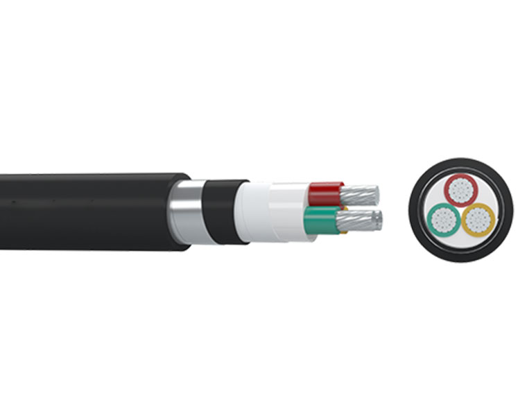
These power cables are used for electricity supply in low voltage installation systems. They are well adapted to underground use in industrial applications with an additional mechanical protection. These cables can be laying indoor, tunnel and underground. Able to bear external mechanical force, but unable to bear large pulling force.
CONSTRUCTION
● Conductor: Aluminum, class 1 or class 2, solid or stranded, circular or circular compacted conductors
● Insulation: Polyvinyl chloride PVC
● Filler: Non-hygroscopic material
● Binder: Non-hygroscopic material
● Inner sheath: Polyvinyl chloride PVC
● Armour: Steel tape
● Outer sheath: Polyvinyl chloride PVC
MAIN CHARACTERRISTICS
Good electrical and mechanical properties. Resistance to abrasion, moisture and sunlight. Adequate resistance to oil and abrasion.
SPECIFICATION
IEC 60228 Conductors of Insulate Cables
IEC 60502-1 Power Cables with Extruded Insulation and Their Accessories for Rated Voltages from 1kV(Um=1.2kV) up to 30kV(Um=36kV) - Part 1: Cables for Rated Voltages of 1kV (Um=1.2kV) and 3kV(Um=3.6kV)
Parameter
IEC 60502-1
| No. of Cores and Nominal Cross Section | Min. Number of Wires | Nominal Insulation Thickness | Nominal | Nominal | Approx. | Approx. Weight | Max. D.C. Resistance of Conductor |
| Steel Tape Thickness | Sheath Thickness | Overall Diameter | at 20℃ | ||||
| No. × mm² | No. | mm | mm | mm | mm | kg/km | Ω/km |
| 2×2.5 | 1 | 0.8 | 0.2 | 1.8 | 13.4 | 246 | 12.1 |
| 2×4 | 1 | 1 | 0.2 | 1.8 | 15.2 | 306 | 7.41 |
| 2×6 | 1 | 1 | 0.2 | 1.8 | 16.2 | 350 | 4.61 |
| 2×10 | 6 | 1 | 0.2 | 1.8 | 18.7 | 429 | 3.08 |
| 2×16 | 6 | 1 | 0.2 | 1.8 | 20.3 | 522 | 1.91 |
| 2×25 | 6 | 1.2 | 0.2 | 1.8 | 23.5 | 684 | 1.2 |
| 2×35 | 6 | 1.2 | 0.2 | 1.8 | 25.5 | 804 | 0.868 |
| 2×50 | 6 | 1.4 | 0.2 | 1.8 | 28.9 | 990 | 0.641 |
| 2×70 | 12 | 1.4 | 0.2 | 1.9 | 32.8 | 1261 | 0.443 |
| 2×95 | 15 | 1.6 | 0.5 | 2.1 | 38.8 | 1990 | 0.32 |
| 2×120 | 15 | 1.6 | 0.5 | 2.2 | 41.8 | 2262 | 0.253 |
| 2×150 | 15 | 1.8 | 0.5 | 2.4 | 46.4 | 2741 | 0.206 |
| 2×185 | 30 | 2 | 0.5 | 2.5 | 50.6 | 3221 | 0.164 |
| 2×240 | 30 | 2.2 | 0.5 | 2.7 | 56.4 | 3945 | 0.125 |
| 2×300 | 30 | 2.4 | 0.5 | 2.9 | 62.4 | 4758 | 0.1 |
| 2×400 | 53 | 2.6 | 0.5 | 3.1 | 69.2 | 5756 | 0.0778 |
| 3×2.5 | 1 | 0.8 | 0.2 | 1.8 | 14 | 271 | 12.1 |
| 3×4 | 1 | 1 | 0.2 | 1.8 | 15.8 | 343 | 7.41 |
| 3×6 | 1 | 1 | 0.2 | 1.8 | 16.9 | 396 | 4.61 |
| 3×10 | 6 | 1 | 0.2 | 1.8 | 19.7 | 491 | 3.08 |
| 3×16 | 6 | 1 | 0.2 | 1.8 | 21.4 | 607 | 1.91 |
| 3×25 | 6 | 1.2 | 0.2 | 1.8 | 24.8 | 808 | 1.2 |
| 3X35 | 6 | 1.2 | 0.2 | 1.8 | 27 | 960 | 0.868 |
| 3×50 | 6 | 1.4 | 0.2 | 1.9 | 30.9 | 1208 | 0.641 |
| 3×70 | 12 | 1.4 | 0.2 | 2 | 35 | 1555 | 0.443 |
| 3×95 | 15 | 1.6 | 0.5 | 2.2 | 41.4 | 2409 | 0.32 |
| No. of Cores and Nominal Cross Section | Min. Number of Wires | Nominal Insulation Thickness | Nominal | Nominal | Approx. | Approx. Weight | Max. D.C. Resistance of Conductor |
| Steel Tape Thickness | Sheath Thickness | Overall Diameter | at 20℃ | ||||
| No. × mm² | No. | mm | mm | mm | mm | kg/km | Ω/km |
| 3×120 | 15 | 1.6 | 0.5 | 2.3 | 44.6 | 2758 | 0.253 |
| 3×150 | 15 | 1.8 | 0.5 | 2.5 | 49.5 | 3348 | 0.206 |
| 3×185 | 30 | 2 | 0.5 | 2.6 | 54 | 3963 | 0.164 |
| 3×240 | 30 | 2.2 | 0.5 | 2.8 | 60.6 | 4957 | 0.125 |
| 3×300 | 30 | 2.4 | 0.5 | 3 | 66.7 | 5925 | 0.1 |
| 3×400 | 53 | 2.6 | 0.5 | 3.3 | 74.6 | 7329 | 0.0778 |
| 4×2.5 | 1 | 0.8 | 0.2 | 1.8 | 14.8 | 307 | 12.1 |
| 4×4 | 1 | 1 | 0.2 | 1.8 | 16.9 | 394 | 7.41 |
| 4×6 | 1 | 1 | 0.2 | 1.8 | 18.2 | 458 | 4.61 |
| 4×10 | 6 | 1 | 0.2 | 1.8 | 21.2 | 573 | 3.08 |
| 4×16 | 6 | 1 | 0.2 | 1.8 | 23.2 | 717 | 1.91 |
| 4×25 | 6 | 1.2 | 0.2 | 1.8 | 27 | 965 | 1.2 |
| 4×35 | 6 | 1.2 | 0.2 | 1.9 | 29.6 | 1169 | 0.868 |
| 4×50 | 6 | 1.4 | 0.2 | 2 | 34.7 | 1527 | 0.641 |
| 4×70 | 12 | 1.4 | 0.5 | 2.2 | 39.9 | 2302 | 0.443 |
| 4×95 | 15 | 1.6 | 0.5 | 2.4 | 46 | 2987 | 0.32 |
| 4×120 | 15 | 1.6 | 0.5 | 2.5 | 49.6 | 3430 | 0.253 |
| 4×150 | 15 | 1.8 | 0.5 | 2.6 | 54.4 | 4086 | 0.206 |
| 4×185 | 30 | 2 | 0.5 | 2.8 | 60 | 4950 | 0.164 |
| 4×240 | 30 | 2.2 | 0.5 | 3 | 67 | 6129 | 0.125 |
| 4×300 | 30 | 2.4 | 0.5 | 3.2 | 74.1 | 7430 | 0.1 |
| 4×400 | 53 | 2.6 | 0.5 | 3.5 | 82.4 | 9112 | 0.0778 |
| 5×2.5 | 1 | 0.8 | 0.2 | 1.8 | 15.8 | 345 | 12.1 |
| 5×4 | 1 | 1 | 0.2 | 1.8 | 18.1 | 447 | 7.41 |
| 5×6 | 1 | 1 | 0.2 | 1.8 | 19.5 | 524 | 4.61 |
| 5×10 | 6 | 1 | 0.2 | 1.8 | 22.9 | 662 | 3.08 |
| 5×16 | 6 | 1 | 0.2 | 1.8 | 25.1 | 834 | 1.91 |
| 5×25 | 6 | 1.2 | 0.2 | 1.9 | 29.6 | 1147 | 1.2 |
| 5×35 | 6 | 1.2 | 0.2 | 1.9 | 33 | 1426 | 0.868 |
| 5×50 | 6 | 1.4 | 0.5 | 2.2 | 39.4 | 2202 | 0.641 |
| No. of Cores and Nominal Cross Section | Min. Number of Wires | Nominal Insulation Thickness | Nominal | Nominal | Approx. | Approx. Weight | Max. D.C. Resistance of Conductor |
| Steel Tape Thickness | Sheath Thickness | Overall Diameter | at 20℃ | ||||
| No. × mm² | No. | mm | mm | mm | mm | kg/km | Ω/km |
| 5×70 | 12 | 1.4 | 0.5 | 2.3 | 43.6 | 2719 | 0.443 |
| 5×95 | 15 | 1.6 | 0.5 | 2.5 | 50.4 | 3539 | 0.32 |
| 5×120 | 15 | 1.6 | 0.5 | 2.6 | 54.3 | 4077 | 0.253 |
| 5×150 | 15 | 1.8 | 0.5 | 2.8 | 60.3 | 4963 | 0.206 |
| 5×185 | 30 | 2 | 0.5 | 3 | 66.1 | 5940 | 0.164 |
| 5×240 | 30 | 2.2 | 0.5 | 3.2 | 74.2 | 7455 | 0.125 |
| 5×300 | 30 | 2.4 | 0.5 | 3.5 | 81.8 | 8990 | 0.1 |
| 5×400 | 53 | 2.6 | 0.8 | 3.8 | 92.2 | 11931 | 0.0778 |
| 3×4+1×2.5 | 1/1 | 1.0/0.8 | 0.2 | 1.8 | 16.4 | 371 | 7.41/12.1 |
| 3×6+1×4 | 1/1 | 1.0/1.0 | 0.2 | 1.8 | 17.9 | 442 | 4.61/7.41 |
| 3×10+1×6 | 6/1 | 1.0/1.0 | 0.2 | 1.8 | 20.5 | 544 | 3.08/4.61 |
| 3×16+1×10 | 6/6 | 1.0/1.0 | 0.2 | 1.8 | 22.7 | 680 | 1.91/3.08 |
| 3×25+1×16 | 6/6 | 1.2/1.0 | 0.2 | 1.8 | 26.1 | 901 | 1.20/1.91 |
| 3×35+1×16 | 6/6 | 1.2/1.0 | 0.2 | 1.8 | 27.9 | 1042 | 0.868/1.91 |
| 3×50+1×25 | 6/6 | 1.4/1.2 | 0.2 | 1.9 | 32.8 | 1373 | 0.641/1.20 |
| 3×70+1×35 | 12/6 | 1.4/1.2 | 0.2 | 2.1 | 36.6 | 1735 | 0.443/0.868 |
| 3×95+1×50 | 6/15 | 1.6/1.4 | 0.5 | 2.3 | 43.2 | 2657 | 0.320/0.641 |
| 3×120+1×70 | 12/15 | 1.6/1.4 | 0.5 | 2.4 | 47.2 | 3145 | 0.253/0.443 |
| 3×150+1×70 | 12/15 | 1.8/1.4 | 0.5 | 2.5 | 50.9 | 3633 | 0.206/0.443 |
| 3×185+1×95 | 30/15 | 2.0/1.6 | 0.5 | 2.7 | 56.2 | 4395 | 0.164/0.320 |
| 3×240+1×120 | 30/15 | 2.2/1.6 | 0.5 | 2.9 | 62.8 | 5449 | 0.125/0.253 |
| 3×300+1×150 | 30/15 | 2.4/1.8 | 0.5 | 3.1 | 69.1 | 6536 | 0.100/0.206 |
| 3×400+1×185 | 53/30 | 2.6/2.0 | 0.5 | 3.3 | 76.9 | 8039 | 0.0778/0.164 |
| 3×4+2×2.5 | 1/1 | 1.0/0.8 | 0.2 | 1.8 | 17.2 | 406 | 7.41/12.1 |
| 3×6+2×4 | 1/1 | 1.0/1.0 | 0.2 | 1.8 | 18.9 | 493 | 4.61/7.41 |
| 3×10+2×6 | 6/1 | 1.0/1.0 | 0.2 | 1.8 | 21.5 | 606 | 3.08/4.61 |
| 3×16+2×10 | 6/6 | 1.0/1.0 | 0.2 | 1.8 | 24.2 | 764 | 1.91/3.08 |
| 3×25+2×16 | 6/6 | 1.2/1.0 | 0.2 | 1.8 | 27.7 | 1011 | 1.20/1.91 |
| 3×35+2×16 | 6/6 | 1.2/1.0 | 0.2 | 1.9 | 29.5 | 1159 | 0.868/1.91 |
| 3×50+2×25 | 6/6 | 1.4/1.2 | 0.2 | 2 | 34.9 | 1560 | 0.641/1.20 |
| No. of Cores and Nominal Cross Section | Min. Number of Wires | Nominal Insulation Thickness | Nominal | Nominal | Approx. | Approx. Weight | Max. D.C. Resistance of Conductor |
| Steel Tape Thickness | Sheath Thickness | Overall Diameter | at 20℃ | ||||
| No. × mm² | No. | mm | mm | mm | mm | kg/km | Ω/km |
| 3×70+2×35 | 12/6 | 1.4/1.2 | 0.5 | 2.2 | 40 | 2322 | 0.443/0.868 |
| 3×95+2×50 | 6/15 | 1.6/1.4 | 0.5 | 2.4 | 46.2 | 3000 | 0.320/0.641 |
| 3×120+2×70 | 12/15 | 1.6/1.4 | 0.5 | 2.5 | 50.3 | 3544 | 0.253/0.443 |
| 3×150+2×70 | 12/15 | 1.8/1.4 | 0.5 | 2.6 | 53.5 | 4016 | 0.206/0.443 |
| 3×185+2×95 | 30/15 | 2.0/1.6 | 0.5 | 2.8 | 59.9 | 4976 | 0.164/0.320 |
| 3×240+2×120 | 30/15 | 2.2/1.6 | 0.5 | 3 | 66.2 | 6050 | 0.125/0.253 |
| 3×300+2×150 | 30/15 | 2.4/1.8 | 0.5 | 3.2 | 72.9 | 7273 | 0.100/0.206 |
| 3×400+2×185 | 53/30 | 2.6/2.0 | 0.5 | 3.5 | 81.2 | 8975 | 0.0778/0.164 |
| 4×4+1×2.5 | 1/1 | 1.0/0.8 | 0.2 | 1.8 | 17.7 | 426 | 7.41/12.1 |
| 4×6+1×4 | 1/1 | 1.0/1.0 | 0.2 | 1.8 | 19.2 | 509 | 4.61/7.41 |
| 4×10+1×6 | 6/1 | 1.0/1.0 | 0.2 | 1.8 | 22.2 | 634 | 3.08/4.61 |
| 4×16+1×10 | 6/6 | 1.0/1.0 | 0.2 | 1.8 | 24.6 | 799 | 1.91/3.08 |
| 4×25+1×16 | 6/6 | 1.2/1.0 | 0.2 | 1.8 | 28.5 | 1072 | 1.20/1.91 |
| 4×35+1×16 | 6/6 | 1.2/1.0 | 0.2 | 1.9 | 30.9 | 1268 | 0.868/1.91 |
| 4×50+1×25 | 6/6 | 1.4/1.2 | 0.2 | 2.1 | 36.5 | 1699 | 0.641/1.20 |
| 4×70+1×35 | 12/6 | 1.4/1.2 | 0.5 | 2.3 | 41.9 | 2529 | 0.443/0.868 |
| 4×95+1×50 | 6/15 | 1.6/1.4 | 0.5 | 2.4 | 48.2 | 3257 | 0.320/0.641 |
| 4×120+1×70 | 12/15 | 1.6/1.4 | 0.5 | 2.6 | 52.4 | 3821 | 0.253/0.443 |
| 4×150+1×70 | 12/15 | 1.8/1.4 | 0.5 | 2.7 | 57.1 | 4514 | 0.206/0.443 |
| 4×185+1×95 | 30/15 | 2.0/1.6 | 0.5 | 2.9 | 63 | 5454 | 0.164/0.320 |
| 4×240+1×120 | 30/15 | 2.2/1.6 | 0.5 | 3.1 | 70 | 6707 | 0.125/0.253 |
| 4×300+1×150 | 30/15 | 2.4/1.8 | 0.5 | 3.3 | 77.4 | 8145 | 0.100/0.206 |
| 4×400+1×185 | 53/30 | 2.6/2.0 | 0.8 | 3.7 | 87.4 | 10858 | 0.0778/0.164 |

