Earth/Ground Rods: Types, Installation, and Their Role in Grounding Systems
Release time: 2025-05-13
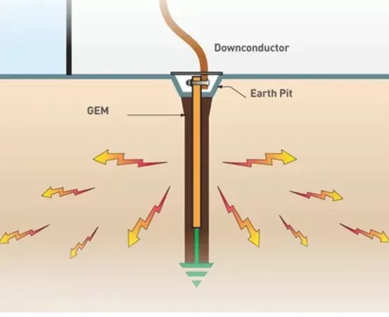
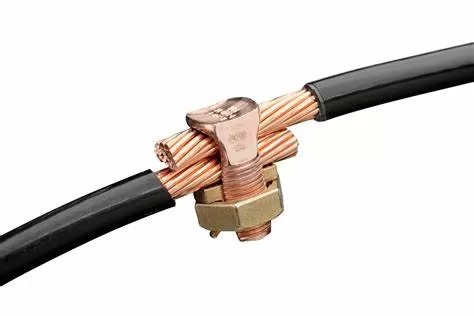
Introduction Earth rods, also known as grounding electrodes, are essential components in electrical systems designed to safely dissipate fault currents into the ground. They protect structures, equipment, and personnel from the hazards of lightning strikes, electrical surges, and short circuits by providing a low-resistance path to earth. What is an Earth Rod? An earth rod is a conductive metal rod driven into the ground to establish a reliable electrical connection with the earth. Typically made from copper, galvanized steel, or copper-bonded steel, these rods ensure that excess electrical current is safely directed away from sensitive systems. Types of Earth Rods Galvanized Earth Rods – Constructed from steel with a zinc coating for corrosion resistance. These are cost-effective and commonly used in general grounding applications. Copper Earth Rods – Offer superior conductivity and corrosion resistance, making them ideal for harsh environments, such as acidic or high-moisture soils. Copper-Bonded Earth Rods – Feature a thick copper layer over a steel core, combining high conductivity with durability and corrosion resistance. Installation of Earth Rods Select the Location – Choose a spot at least 2 feet away from a building’s foundation to avoid structural interference. Excavate the Ground – Dig a hole 2-4 feet deep and wide enough for rod placement. Drive the Rod – Using a hammer or specialized driving tool, install the rod vertically to a minimum depth of 8 feet to ensure contact with moist soil. Connect the Grounding Conductor – Securely attach a grounding electrode conductor (typically copper wire) to the rod using a corrosion-resistant clamp. Link to the Electrical System – Route the conductor to the main electrical panel, ensuring a solid connection. Determining the Number of Earth Rods Required The quantity depends on factors such as: Soil resistivity (higher resistance may require additional rods). Electrical load and system requirements. Local electrical codes (typically 3 to 15 rods spaced at least 3 meters apart, interconnected with grounding cable). Optimal Depth for Earthing Rods Earth rods should penetrate deep enough to reach permanently moist soil layers, usually at least 8 feet (2.4 meters). Deeper installation may be necessary in dry or rocky soils to achieve an effective ground connection. Connecting Earth Wire to an Earth Rod Use a high-quality ground rod clamp to attach the grounding conductor (bare copper or insulated wire) to the rod. Ensure a tight, corrosion-resistant connection to maintain low resistance. Route the conductor to the main grounding busbar in the electrical panel. Testing Earth Rod Effectiveness To verify proper grounding: Use a clamp-on ground resistance tester or an earth electrode tester to measure resistance (ideally below 25 ohms for most applications). Regular testing ensures long-term reliability, especially in corrosive or high-resistance soil conditions. Conclusion Earth rods are a fundamental part of any effective grounding system, safeguarding electrical installations from faults and surges. Proper selection, installation, and maintenance—including periodic resistance testing—are crucial for ensuring optimal performance and safety. By adhering to industry standards and local regulations, a well-designed grounding system can significantly enhance electrical safety and system reliability.